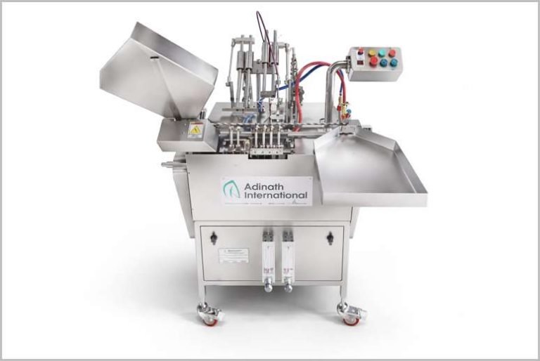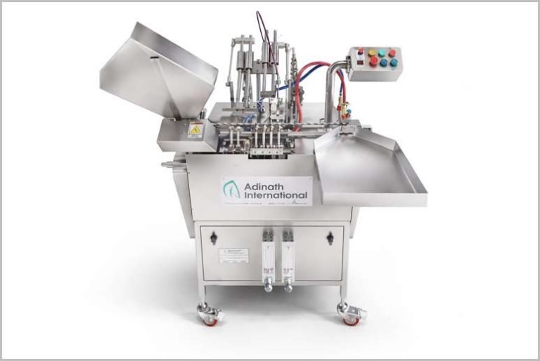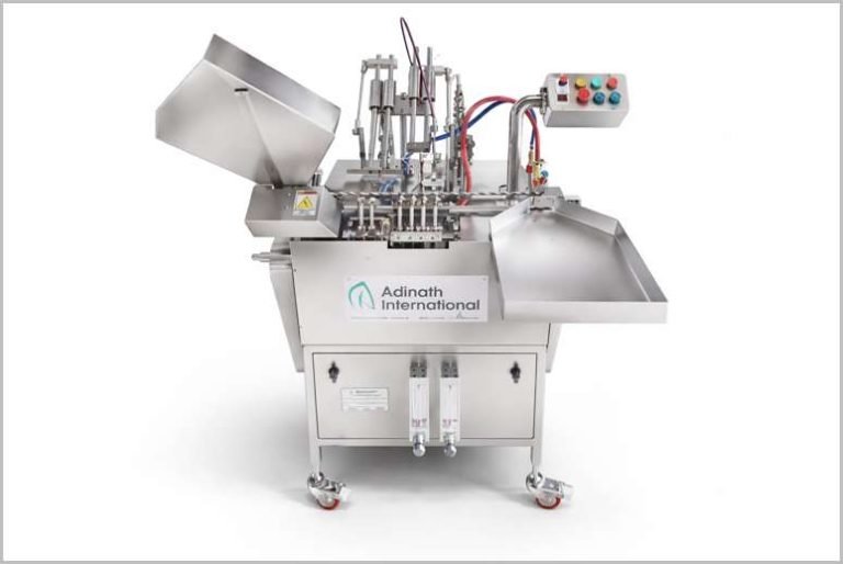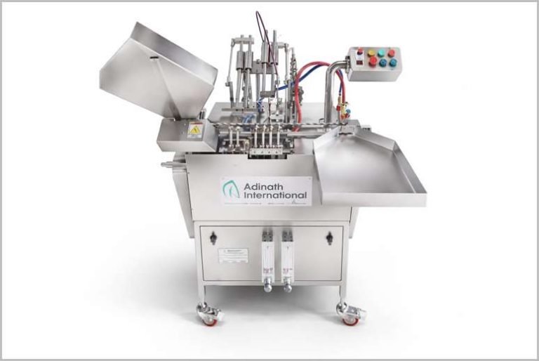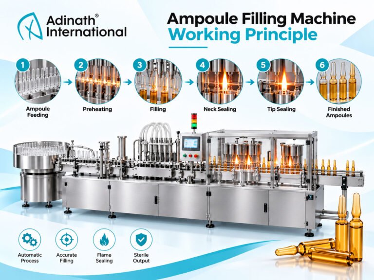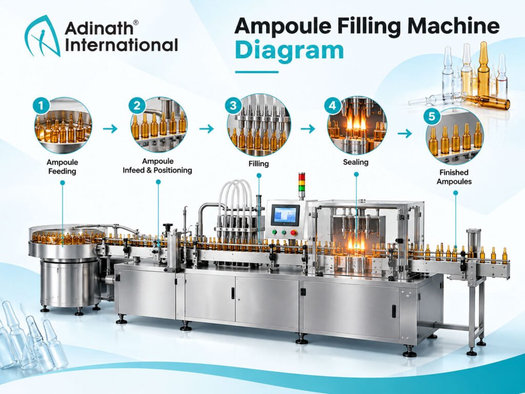
A drawing is often the quickest way to understand a machine you have not yet stood next to. This article walks through an ampoule filling machine diagram station by station, so that you can match each numbered part to its job and see how an empty ampoule travels from the infeed hopper to the collection tray. It is written for production engineers, maintenance staff and buyers who read layout drawings during installation planning, training or a purchase evaluation.
The diagram described here represents a typical linear filler-sealer, the most common design for glass ampoules. Exact positions, the number of heads and some optional stations vary between models, so treat the figure as a guide to reading any manufacturer’s drawing rather than as a dimensioned drawing of one machine. If you want to compare actual models while you read, you can see our ampoule filling machines.
How to read the ampoule filling machine diagram
The figure below shows two views of the same machine. The side view shows heights: the hopper above the transport, the needles and burners above the ampoule path, and the drive below the table top. The top view shows the order of stations along the ampoule path, from left to right. Each part carries the same number in both views, and Table 1 lists every number with its function.
| No. | Part | Function |
|---|---|---|
| 1 | Infeed hopper | Holds washed, sterilised empty ampoules and feeds them downwards |
| 2 | Star wheel or receiving rack | Separates ampoules and presents them one by one to the transport |
| 3 | Moving transport rack | Lifts and steps a group of ampoules forward from station to station |
| 4 | Pre-gassing nozzles | Purge the empty ampoule with inert gas (optional) |
| 5 | Dosing syringes and valves | Measure and deliver the set fill volume |
| 6 | Filling needles and needle carriage | Enter the ampoule neck and deliver the liquid inside it |
| 7 | Post-gassing nozzles | Flush the headspace above the liquid (optional) |
| 8 | Pre-heating burners | Warm the neck gradually before sealing |
| 9 | Sealing burners | Soften the glass enough for the neck to close |
| 10 | Rotating rollers | Turn each ampoule so the neck heats evenly |
| 11 | Pull-sealing jaws | Grip and draw off the softened tip (on pull-seal machines) |
| 12 | Waste tip collector | Receives the glass tips removed during pull sealing |
| 13 | Outfeed and collection tray | Collects sealed ampoules without knocking them together |
| 14 | Main drive and cam shaft | Moves every station in one synchronised cycle |
| 15 | Control panel and gas flow meters | Start, stop and speed control; burner and purge gas setting |
When you read any ampoule filling machine diagram, three questions help. Follow the ampoule path: where does it enter, where is it held still, and where does it leave? Identify everything that touches the product, because those parts set cleaning and material requirements. Then find the utilities: power, fuel gas, oxygen and inert gas.
Infeed hopper and ampoule transport (parts 1–3)
The infeed hopper (1) sits at the left of the top view and above the table in the side view. Washed and sterilised ampoules are loaded into it, either directly from a sterilising tunnel or from trays. Its floor is usually sloped so that ampoules roll or slide towards the outlet under gravity, and side plates keep them parallel. On a complete line the hopper is fed by upstream equipment, typically an ampoule washing machine and a sterilising tunnel.
At the hopper outlet, a star wheel or receiving rack (2) separates the ampoules. A star wheel is a rotating disc with pockets cut to the ampoule diameter; each pocket picks up one ampoule and carries it to the transfer position. Some designs use a cassette or a slotted receiving rack instead. Either way, the job is to turn a crowded mass of ampoules into a row at a fixed pitch.
The moving transport rack (3) then takes over. On many filler-sealers it is a pair of serrated racks driven by an eccentric or cam: one rack is fixed, the other lifts the ampoules, moves them forward by one pitch and sets them down again. This “walking beam” action moves a group equal to the number of heads at each step and holds them still while an operation takes place. Some designs carry the ampoules at an incline so that the open neck tilts towards the needles and burners.
Parts 2 and 3 touch the ampoule body, so they are size-specific. On the drawing they are usually marked as change parts, often with a separate list of the ampoule formats they cover.
Filling station: syringes and needles (parts 5–6)
In the side view, the filling station sits above the ampoule path, roughly in the middle of the machine. It has two groups of parts that are drawn separately but work together.
Dosing syringes and valves (5)
Each head has one dosing syringe, a precision cylinder in glass or stainless steel with a plunger. A push rod links the plunger to the drive, and a stroke adjustment sets the volume delivered per cycle. On the drawing you will normally see the syringes mounted in a row on a common bracket, with inlet tubing running from a product vessel or manifold and outlet tubing running to the needles. Non-return valves at the syringe outlet make sure liquid flows only towards the needles.
Filling needles and needle carriage (6)
The filling needles are mounted on a carriage that moves up and down in time with the transport. When a group of ampoules arrives under the station, the carriage lowers the needles into the necks, the syringes deliver, and the carriage lifts again before the rack moves. In the top view the needles line up exactly with the ampoule positions at that station, which is why the needle block, like the transport, may need changing or re-setting for a different ampoule size.
A small sensing device near this station is often shown as well. It detects a missing ampoule and prevents that head from dosing, so liquid is not sprayed onto the machine. Single-head and two-head layouts follow exactly the same arrangement with fewer syringes; our Two Head Ampoule Filling Machine is an example of a compact layout where every station is easy to see.
Gas flushing nozzles (parts 4 and 7)
Gas nozzles appear on either side of the filling station. Pre-gassing nozzles (4), placed before filling, blow an inert gas, most commonly nitrogen, into the empty ampoule to displace air. Post-gassing nozzles (7), placed after filling, flush the headspace above the liquid just before sealing. Some layouts also allow gassing during filling.
On the diagram the nozzles look like filling needles and often share their carriage, but thin gas tubes run back to a filter and flow meter rather than to a syringe. Because purging is product-dependent, a drawing may show these nozzles as optional, or the stations may be present but left unused for products that do not need an inert atmosphere.
Sealing station and burners (parts 8–12)
The sealing station is usually at the right-hand end of the top view, just before the outfeed. It is where the drawing becomes most crowded, because burners, rollers and jaws sit very close to the ampoule necks.
Pre-heating and sealing burners (8, 9)
The pre-heating burners (8) warm the neck gradually so that the glass does not crack from sudden heating. The sealing burners (9) then deliver a hotter, more concentrated flame that softens the glass enough to close. Each burner is fed from a manifold that mixes a fuel gas with oxygen. Adinath product pages list LPG and oxygen as the burner gases. Burner nozzles are usually drawn as small blocks angled towards the neck.
Rotating rollers (10)
Beneath the burners, rollers (10) spin each ampoule on its own axis while the neck is in the flame. Even rotation gives even heating all the way round, which is essential for a symmetrical seal. In the side view the rollers appear just below the ampoule bodies, driven by a belt or gears from the main drive.
Pull-sealing jaws and waste tip collector (11, 12)
On pull-seal machines, a pair of jaws (11) closes on the softened tip and draws it away, stretching the glass until it fuses into a rounded end. The removed tips fall into a waste tip collector (12), which keeps broken glass away from the ampoule path. On tip-seal (fusion) machines, the jaws and collector are absent, because the tip is melted closed without pulling. You can see how filling and sealing are combined on one frame in the Ampoule Filling and Sealing Machine range.
Drive, cams and control panel (parts 14–15)
The main drive and cam shaft (14) are hidden below the table in the side view, usually behind access panels. A motor drives a gearbox and a shaft carrying cams. Each cam is shaped to give one movement at the right moment: lifting the transport rack, lowering the needle carriage, driving the syringe plungers and closing the sealing jaws. Because every cam is on the same shaft, or linked to it, all stations stay in step. Some designs use servo motors for selected movements instead of mechanical cams.
The control panel (15) is usually drawn on the operator side. It carries the main switch, start and stop controls, speed adjustment, counters and emergency stop. Close to it, or on the side of the frame, sits the gas panel: flow meters and valves for fuel gas, oxygen and nitrogen. Placing these where the operator can see the flame while adjusting them is a deliberate layout choice.
Outfeed and collection (part 13)
At the end of the transport, sealed ampoules are pushed onto an outfeed or collection tray (13). The sealed tips are still hot, so the tray collects ampoules gently, often upright. On a line, a conveyor may carry them on to inspection and labelling instead.
One machine design can often handle several ampoule sizes by fitting the matching change parts for the star wheel, transport rack and needle block.
Single-head and multi-head layouts compared
The order of stations does not change as heads are added; the stations simply become wider. Table 2 summarises what changes on the drawing.
| Feature | Single or two heads | Four or more heads |
|---|---|---|
| Transport | Steps one or two ampoules per cycle | Steps a larger group per cycle |
| Syringes and needles | One or two, easy to reach | A row on a common bracket |
| Gas nozzles and burners | Few, often in one block | Multiplied for each head position |
| Footprint | Compact, often bench-height frame | Longer and wider frame |
| Typical use | Laboratory, pilot and small batches | Commercial production |
Because the stations are repeated for each head position, the number of gas nozzles and burners on a multi-head drawing grows with the number of heads; the exact counts for a model are given in its technical specification. Comparing drawings of machines with different head counts side by side is the quickest way to see this.
From diagram to installed line
For installation planning, the ampoule filling machine diagram is combined with drawings of the upstream washer and steriliser and the downstream inspection and labelling equipment, so that heights, conveyor directions and operator access match. Planning the filler as part of a complete pharmaceutical filling line from the start avoids mismatched heights and transfer points later.
Conclusion
An ampoule filling machine diagram becomes easy to read once you follow the ampoule path: hopper and star wheel at the start, a stepping transport rack, gas nozzles either side of the syringes and needles, burners with rollers and jaws at the sealing station, and a collection tray at the end, all driven by one cam shaft below the table and set from a control panel and gas flow meters. The same order applies whether the drawing shows one head or eight.
If you would like a layout drawing for a specific model, or help checking a drawing against your room, our team can assist. Send us an enquiry with your ampoule sizes, fill volumes and room dimensions.
 Summarize this article with: